attiny85是一个入门的8位单片机, 可以使用digispark库进行开发. 可以实现简单的逻辑控制.
Features
• High Performance, Low Power AVR® 8-Bit Microcontroller
• Advanced RISC Architecture
– 120 Powerful Instructions – Most Single Clock Cycle Execution
– 32 x 8 General Purpose Working Registers
– Fully Static Operation
• Non-volatile Program and Data Memories
– 2/4/8K Bytes of In-System Programmable Program Memory Flash
• Endurance: 10,000 Write/Erase Cycles
– 128/256/512 Bytes In-System Programmable EEPROM
• Endurance: 100,000 Write/Erase Cycles
– 128/256/512 Bytes Internal SRAM
– Programming Lock for Self-Programming Flash Program and EEPROM Data Security
• Peripheral Features
– 8-bit Timer/Counter with Prescaler and Two PWM Channels
– 8-bit High Speed Timer/Counter with Separate Prescaler
• 2 High Frequency PWM Outputs with Separate Output Compare Registers
• Programmable Dead Time Generator
– USI – Universal Serial Interface with Start Condition Detector
– 10-bit ADC
• 4 Single Ended Channels
• 2 Differential ADC Channel Pairs with Programmable Gain (1x, 20x)
• Temperature Measurement
– Programmable Watchdog Timer with Separate On-chip Oscillator
– On-chip Analog Comparator
• Special Microcontroller Features
– debugWIRE On-chip Debug System
– In-System Programmable via SPI Port
– External and Internal Interrupt Sources
– Low Power Idle, ADC Noise Reduction, and Power-down Modes
– Enhanced Power-on Reset Circuit
– Programmable Brown-out Detection Circuit
– Internal Calibrated Oscillator
• I/O and Packages
– Six Programmable I/O Lines
– 8-pin PDIP, 8-pin SOIC, 20-pad QFN/MLF, and 8-pin TSSOP (only ATtiny45/V)
• Operating Voltage
– 1.8 - 5.5V for ATtiny25V/45V/85V
– 2.7 - 5.5V for ATtiny25/45/85
• Speed Grade
– ATtiny25V/45V/85V: 0 – 4 MHz @ 1.8 - 5.5V, 0 - 10 MHz @ 2.7 - 5.5V
– ATtiny25/45/85: 0 – 10 MHz @ 2.7 - 5.5V, 0 - 20 MHz @ 4.5 - 5.5V
• Industrial Temperature Range
• Low Power Consumption
– Active Mode:
• 1 MHz, 1.8V: 300 µA
– Power-down Mode:
• 0.1 µA at 1.8V
Digistump
http://digistump.com/wiki/digispark
First, in Arduino IDE, add link below to “Board Manager URL” in Preferences:
http://digistump.com/package_digistump_index.json
Second, download and install ATtiny85 module driver by Digistump:
https://github.com/digistump/DigistumpArduino/releases
after you finish the sketch, you can click the download button.
once it suggest to plugging in the board, do plugin the tiny board into usb hub.
once it finished the flasing, it will print complete message.
prepare
Digispark ATtiny 85
Arduino IDE 1.8.4 (parrot 中的ide是2.x版本的没有Board Manager)
https://www.arduino.cc/en/Main/Software
Digispark驱动程序 (Windows)
https://github.com/digistump/DigistumpArduino/releases
Pin Layout
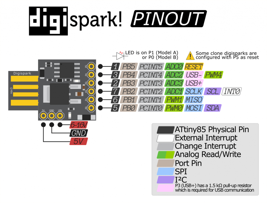
// ATMEL ATTINY85 / ARDUINO
//
//                           +-\/-+
//  Ain0       (D  5)  PB5  1|    |8   VCC
//  Ain3       (D  3)  PB3  2|    |7   PB2  (D  2)  INT0  Ain1
//  Ain2       (D  4)  PB4  3|    |6   PB1  (D  1)        pwm1
//                     GND  4|    |5   PB0  (D  0)        pwm0
//                           +----+
Setup
打开 文件->首选项
把这个网址添加到附加开发板管理网址
https://raw.githubusercontent.com/digistump/arduino-boards-index/master/package_digistump_index.json
点击确定(好)
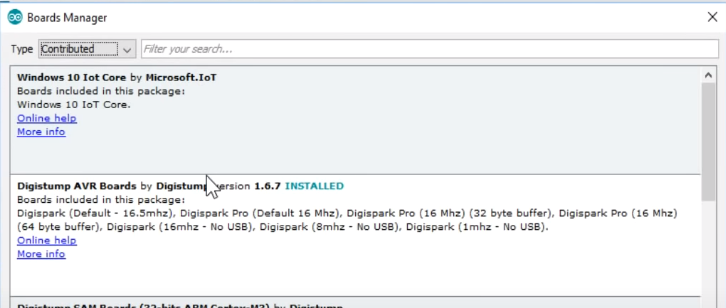
然后打开开发板管理器
这时会自动更新一些东西,建议挂上代理,不然很慢
在Arduino中添加Digispark的支持 等待开发板管理器加载完成,搜索digistump并安装第一个 Digistump AVR Boards
等待安装完成,完成后会有绿色表示
安装Windows下的驱动 打开上面的链接,下载 Digistump.Drivers
解压后执行 Install Drivers.exe 即可
Serial Output
using ftdi to communicate with digispark.
graph LR
AT85[Digispark]
FDTI[FDTI]
AT85--TX_P2->RX---FDTI
AT85--GND->GND---FDTI
AT85--VCC->5V---FDTI
void setup() {
  pinMode(1, OUTPUT);
  Serial.begin(115200);
}

// the loop routine runs over and over again forever:
void loop() {
  digitalWrite(1, HIGH);
  delay(500);
  digitalWrite(1, LOW);
  delay(500);
  Serial.println("I'm alive");
}
using PUTTY to connect com port and set bit
SoftSerial
#include <SendOnlySoftwareSerial.h>

#define SOFTSERIAL_TX 4
#define BUILT_IN_LED 1
SendOnlySoftwareSerial mySerial(SOFTSERIAL_TX);//设置tx pin

void setup() {
  mySerial.begin(9600);
  pinMode(BUILT_IN_LED, OUTPUT);
  digitalWrite(BUILT_IN_LED, LOW);
  Serial.println(F("setup complete"));
}

// the loop routine runs over and over again forever:
void loop() {
  static unsigned long counter = 0;
  mySerial.print(F("this is iteration:"));
  mySerial.println(++counter);
  if(counter%2==0) {
      digitalWrite(BUILT_IN_LED, HIGH);
  } else {
      digitalWrite(BUILT_IN_LED, LOW);
  }
  delay(500);
}
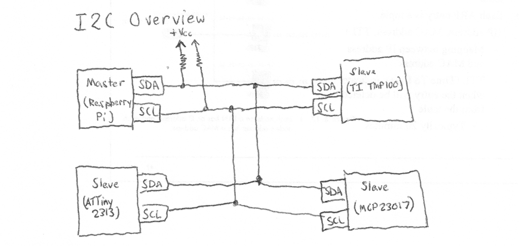
I2C
I2C Wire lib
http://gammon.com.au/i2c
背景
使用 Arduino 例程的时候发现,官方的描述不太详细,走了些弯路。特此,写篇文章记录下。
Arduino 的 I2C 相关函数 Arduino 的封装库真的是非非非常的棒,I2C 就只有 10 个 API 函数。I2C 所用的库,称为:Wire Library。详细的描述可以看这个官方地址:
https://www.arduino.cc/en/Reference/Wire
下面我会介绍部分的 API 函数。
begin
begin 函数用于初始化 Wrie Library 并以 Master 或 Slave 的身份加入 I2C 总线上。begin 函数没有返回值。调用 begin 函数有两种形式:
begin():无输入参数,表示以 Master 形式加入总线。 begin( address ):有输入参数,表示以从机形式加入总线,设备地址为address(7-bit)
beginTransmission
beginTransmission 函数用于启动一次 Master write to Slave 操作。值得注意的是这个函数的调用并不会产生 Start 信号 和发送 Slave Address,仅是实现通知 Arduino后面要启动 Master write to Slave 操作。
beginTransmission 函数调用后,(再调用 write 函数进行数据写入), 最后再调用 endTransmission 函数方能产生 Start 信号 和发送 Slave Address 及通讯时序。 beginTransmission 函数调用形式:
beginTransmission(address) 1
write
write 函数用于向 Slave 写入数据。共有 3 种调用形式:
write(value) :写入单字节 write(string) :写入字符串 write(data, length) :写入 length 个字节
endTransmission
endTransmission 函数用于结束一次 Master write to Slave 操作。前面在介绍 beginTransmission 的时候也介绍过了,如果不在后面使用 endTransmission 函数, 总线上不会产生 Master write to Slave 的时序。
endTransmission 函数的调用十分有意思。endTransmission 函数可输入参数。
endTransmission(0):当输入参数为 0 时,将在通讯结束后,不产生 STOP 信号。 endTransmission(!0):当输入参数为 !0 时,在通讯结束后,生成 STOP 信号。(释放总线) endTransmission():当无输入参数时,在通讯结束后,产生 STOP 信号。(释放总线) 因为我设计的产品程序是使用 DUMMY WRITE 时序,就是这个不产生 STOP 信号卡了我半天的时间(这是我要写本文的原因……)。而官方中,并没有详细介绍这个输入参数…
同时,endTransmission 函数时具有返回值的:
0:success 1:data too long to fit in transmit buffer 2:received NACK on transmit of address 3:received NACK on transmit of data 4:other error 有个地方需要注意的:当通讯过程中,出现异常后,异常后的 write 操作将被终止,直接结束通讯,具体的是否出现异常,只需要看 endTransmission 的返回值即可。
requestFrom
requestFrom 函数用于实现 Master Read From Slave 操作。调用形式有 2 种:
requestFrom(address, quantity):从 address 设备读取 quantity 个字节,结束后,产生 STOP 信号 requestFrom(address, quantity, stop) :从 address 设备读取 quantity 个字节,结束后,依据 stop 的值确定是否产生 STOP 信号。 stop = 0:不产生 STOP 信号 stop != 0:产生 STOP 信号 requestFrom 函数具有返回值(表示从 address 设备读取到的字节数)。
available
available 函数用于统计 Master Read From Slave 操作后, read 缓存区剩余的字节数。每当缓存区的数据被读走 1 个字节,available 函数的返回值减一。通常 available 函数会搭配着 read 函数使用。
read
read 函数用于在 Master Read From Slave 操作后,读取缓存区的数据。
例程
参考例程: https://github.com/TFmini/TFmini-I2C-MasterExample_Arduino
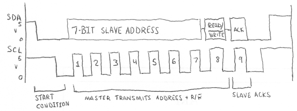
通讯时序如下图所示:
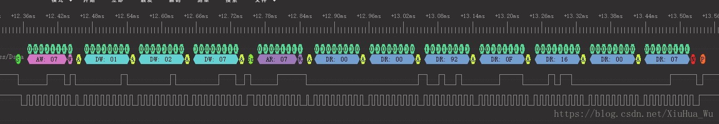
节选代码段:
#include <Wire.h> // I2C head file

void setup() {
  // put your setup code here, to run once:
  Serial.begin(115200);
  // Initiate the Wire library and join the I2C bus as a master or Slave.
  Wire.begin();
  Serial.print("Ready to Read TFmini\r\n");
  delay(10);
}

void loop() {
  // put your main code here, to run repeatedly:
  byte i = 0;
  byte rx_Num = 0;  // the bytes of received by I2C
  byte rx_buf[7] = {0}; // received buffer by I2C

  Wire.beginTransmission(7); // Begin a transmission to the I2C Slave device with the given address.
  Wire.write(1); // Reg's Address_H
  Wire.write(2); // Reg's Address_L
  Wire.write(7); // Data Length
  Wire.endTransmission(0);  // Send a START Sign

  // Wire.requestFrom(AA,BB);receive the data form slave.
  // AA: Slave Address ; BB: Data Bytes
  rx_Num = Wire.requestFrom(0x07, 7);

  // Wire.available: Retuens the number of bytes available for retrieval with read().
  while( Wire.available())
  {
      rx_buf[i] = Wire.read(); // received one byte
      i++;
  }

}
总结
I2C 设备扫描
OLED Display
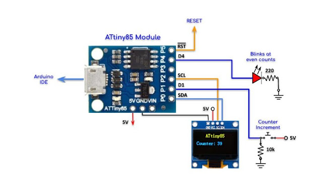
//----------------------------------------
//ATtiny85 Module Interfaced with I2C OLED
//----------------------------------------
#include <DigisparkOLED.h>
#include <Wire.h>
//---------------------------------------------------
#define SW  1
#define LED 4
unsigned int i = 0;
//===================================================
void setup()
{
  pinMode(SW,INPUT);
  pinMode(LED,OUTPUT);
  oled.begin();
  oled.clear();
  oled.setFont(FONT8X16);
  oled.setCursor(30, 0);
  oled.print("ATtiny85");
}
//===================================================
void loop()
{
  if(digitalRead(SW) == HIGH) {
      delay(100);
      i++;
  }
  if(i%2 == 0) digitalWrite(LED, !digitalRead(LED));
  if(i%2 == 1) digitalWrite(LED, LOW);
  //-------------------------------------------------
  oled.setFont(FONT8X16);
  oled.setCursor(0, 3);
  oled.print("Counter: ");
  oled.setCursor(70, 3);
  oled.println(i);
  delay(200);
}
https://akuzechie.blogspot.com/
http://gammon.com.au/i2c
I2C sample
https://www.instructables.com/ATTiny-USI-I2C-The-detailed-in-depth-and-infor/
SPI
http://www.gammon.com.au/spi
SPI-based 0.96″ OLED display
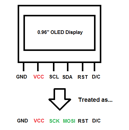
Using Adafruit’s SSD1306 128×64 SPI sample sketch as an example, we would connect the display with the Arduino accordingly:
| Arduino Pins | OLED Display Pins |
|---|---|
| Vcc | Vcc |
| GND | GND |
| D10 | SCL |
| D9 | SDA |
| D13 | RST |
| D11 | D/C |
Download the following libraries & place it in your Arduino Librariy directory:
Adafruit’s GFX library: https://github.com/adafruit/Adafruit-GFX-Library
Adafruit’s SSD1306 library: https://github.com/adafruit/Adafruit_SSD1306
After that, upload the Adafruit’s SSD1306 128×64 SPI sample sketch into your Arduino board & the display should be running!
Sensors
Ultrasonic
#include <SendOnlySoftwareSerial.h>

#define TRIGGER_PIN 0 //HCR04 Trigger set to pin 0
#define ECHO_PIN 2 	// HCR04 Echo set to Pin 2
#define UART_PIN 3
#define BUILT_LIGHT 1

SendOnlySoftwareSerial mySerial(UART_PIN);

void setup() {
  mySerial.begin(9600);
  pinMode(BUILT_LIGHT, OUTPUT);
  digitalWrite(BUILT_LIGHT, LOW);

  pinMode(TRIGGER_PIN, OUTPUT);
  pinMode(ECHO_PIN, INPUT);

  mySerial.println(F("setup complete"));
}

long microsecondsToCentimeters(long microseconds){
  return microseconds / 29 / 2;
}

// the loop routine runs over and over again forever:
void loop() {
  static unsigned long counter = 0;
  long duration, cm;

  digitalWrite(TRIGGER_PIN, LOW);
  delayMicroseconds(2);

  digitalWrite(TRIGGER_PIN, HIGH);
  delayMicroseconds(10);
  digitalWrite(TRIGGER_PIN, LOW);

  duration = pulseIn(ECHO_PIN, HIGH);

  cm = microsecondsToCentimeters(duration);

  mySerial.print(F("distance:"));
  mySerial.println(cm);
  if((counter++)%2 == 0) {
      digitalWrite(BUILT_LIGHT, HIGH);
  } else {
      digitalWrite(BUILT_LIGHT, LOW);
  }
  delay(1000);
}
Low Power
http://brownsofa.org/blog/2011/01/09/the-compleat-attiny13-led-flasher-part-3-low-power-mode/
AVR Libc
https://www.nongnu.org/avr-libc/user-manual/pages.html
Arduino Guide
Arduino教程——使用和编写类库 http://www.arduino.cn/thread-22293-1-1.html Arduino教程——通过 库管理器 添加库 http://www.arduino.cn/thread-31719-1-1.html Arduino教程——手动添加库并使用 http://www.arduino.cn/thread-31720-1-1.html Arduino教程——编写Arduino类库(1) http://www.arduino.cn/thread-31721-1-1.html Arduino教程——编写Arduino类库(2) http://www.arduino.cn/thread-31722-1-1.html Arduino教程——编写Arduino类库(3) http://www.arduino.cn/thread-31723-1-1.html
Refference
Atmel-2586-AVR-8-bit-Microcontroller-ATtiny25-ATtiny45-ATtiny85_Datasheet.pdf
Datasheet: ATTiny 85 Datasheet
Drivers: drivers
Board Manager: package_digistump_index.json
文档信息
- 本文作者:Kiah Zhao
- 本文链接:/2022/05/08/digispark_attiny85/
- 版权声明:自由转载-非商用-非衍生-保持署名(创意共享3.0许可证)
